Predicting Realistic Crack Growth Paths in Welds
Our team at SKC Engineering specializes in weld engineering and their mission is to help our clients obtain the perfect weld for their application. Unfortunately, in the real world achieving this idea can sometimes be elusive, chiefly for field repairs or when welding non-standard materials. At the same time the acceptance & rejection criteria in most welding standards are based on the concept of good workmanship, i.e. what level of defects could be reasonably expected from someone skilled in their craft, and not on what the weld can actually tolerate. Of all possible weld defects, cracks & linear indications (Lack Of Fusion, Incomplete Penetration etc) are considered the most detrimental, especially for applications that are subjected to cyclical (fatigue) loading. So, what can you do if your weld contains linear defects, but repair or replacement is not an option? Fortunately, with modern computing 3-dimensional modeling of crack propagation in welded joints is now a reality allowing for realistic predictions of the life of defective welds.
Crack Growth Basics
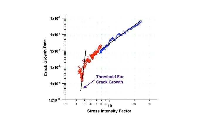
Fatigue Crack Growth Rates in different materials can be measured in the laboratory using specialized equipment. The results of a typical crack growth experiment are illustrated in Figure 1 with crack growth rate shown as a function of the Stress Intensity Factor at the crack tip. It can be seen that up to a threshold a crack will not grow and can be safely tolerated by the material. However, above this threshold crack growth rates increase exponentially. The Stress Intensity Factor at the crack tip can be calculated by embedding a crack into a Finite Element Model of the structure under consideration and subjecting it to actual loading conditions. In the simplest crack growth models the crack length is manually incremented in 1-dimension, and the number of fatigue cycles needed to drive crack growth can then be calculated using the experimental data for crack growth rate.
Realistic Crack Growth Paths
The model described gives a simple way to model a linear crack growth path. However, in reality cracks don’t always grow in straight lines. To extend the model to determine 3-dimensional crack growth paths a number of additional factors have to be taken into account:
- Initial defect size & orientation
- Differences in crack growth rates in weld metal, Heat Affected Zones & base metal
- Variations in Stress Intensity Factor along the 3-dimensional crack front as it propagates (i.e. not just at the crack tip)
- Realistic loading scenarios
To this end, our team at SKC Engineering has developed custom software to fully automate the simulation of 3-dimensional crack paths. Using this software in combination with inspection & non-destructive testing data collected by the team at Applus+ RTD, we uniquely placed to provide the best possible life predictions for defective welds.
Our solutions include:
- Advanced flaw detection & sizing using state of the art radiographic & ultrasonic processes
- Remote strain gauging solutions to collect and monitor loading data
- Laboratories capable of measuring Fatigue Crack Growth Rate data for non-standard materials
- Experience developing all weld metal Fatigue Crack Growth Rate samples, including welding simulation to ensure samples have the same microstructural properties as actual welds in the field
- Advanced crack growth algorithms constructed with different weld and base metal properties including crack growth laws and fracture properties that can dynamically predict evolution of the crack front in 4-dimensions
Example Crack Growth In a 3D Piping Model
The video below shows the 3-dimensional evolution of a crack in a steel pipe girth weld under mixed fatigue loading. The model uses different crack growth rates for the base metal and the weld metal. As such the model captures the transient change in the Stress Intensity Factor along the crack front as in propagates into the parent material. Using this advance algorithm, the dynamic shape of crack can be predicted.
Using the results from the simulation we were able to determine a number of critical factors to allow for effective decision making related to the integrity of the pipe including the service time before the crack started to grow, service time for the crack to break the surface (leak before break criteria), and the total time to final fracture. This example shows that a fracture critical region, i.e. the weld, can be precisely analyzed and life can be estimated to provide a realistic service life prediction for a defective weld.